RPM
The pedal sets spindle speed linearly up to the setpoint, 0–1000 rpm, with a 3 % dead zone. Direction reverses on the fly through zero.
SPEED CONTROL ↗
A brushless motor with field-oriented control turns a Ø102 mm three-jaw chuck at 0–1000 rpm through a 2:1 belt. The foot pedal sets speed, motor torque or rotation angle. A stepper-driven thread guide can follow the spindle at 0.05–20 turns per mm. The housing, chuck and rod supports are 3D-printed parts.
First production batch · preorders open · no payment now
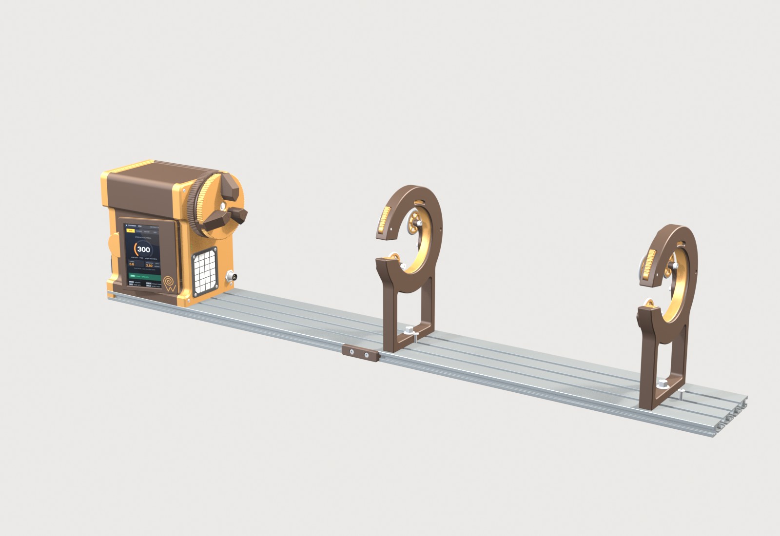 FIG. 01 / FRW4 ASSEMBLY
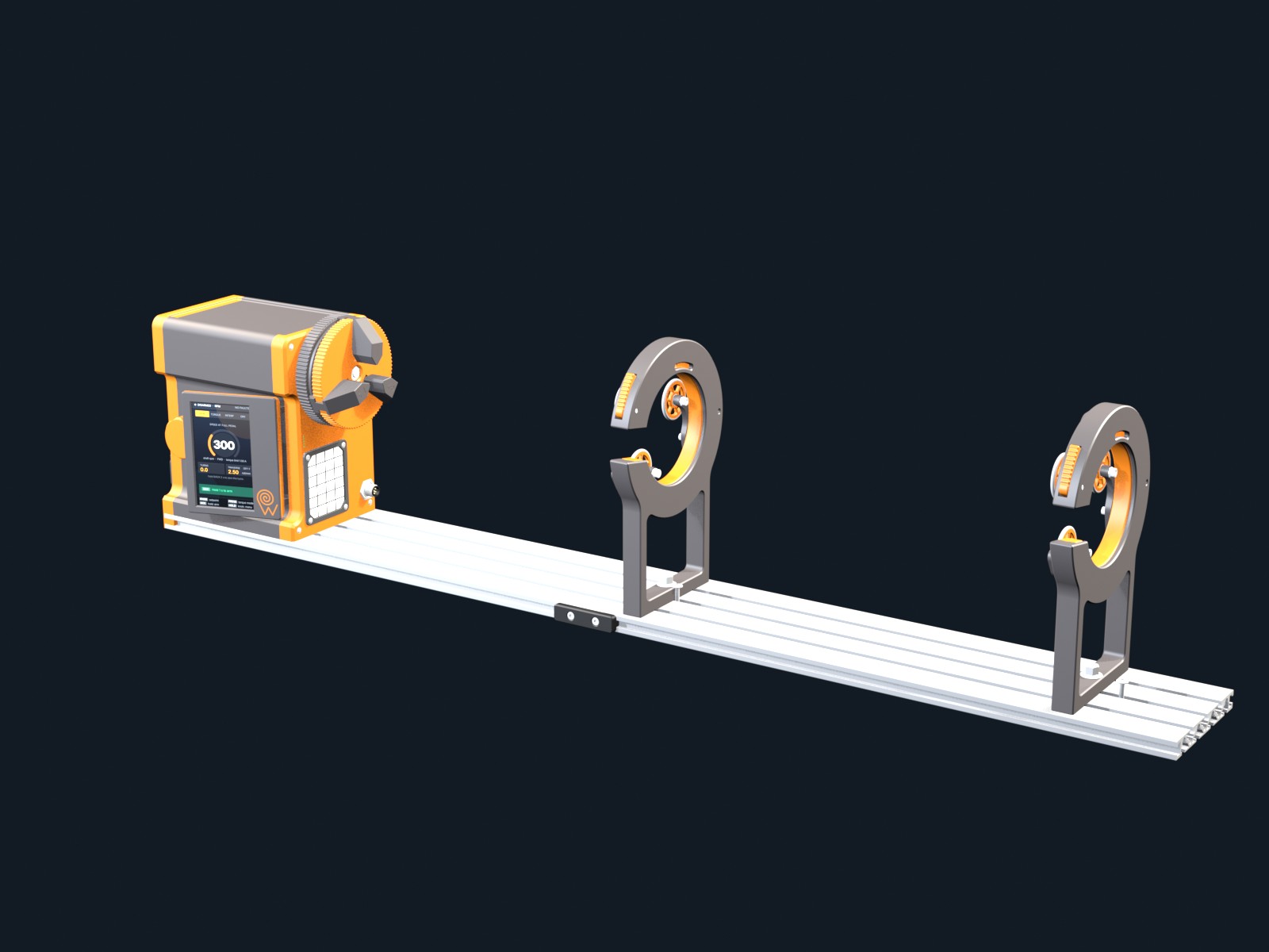
Assembled machine. The simulator drives the real spindle, jaws, motor, display and pedal.
True section through the spindle axis is a pre-rendered view of derived copies.
Rendered from the FRW CAD.
The simulator runs the firmware 4.0 menu logic in the browser. Use the virtual knob and pedal to change modes and settings; the spindle, jaws, motor, display and pedal of the 3D model move with it.
The real CAD parts move with the training simulator: spindle and chuck, the three jaws, the motor rotor at 2:1, the display on its hinge, and the pedal actuator plate (inset). Pivots come from the CAD. The traverse carriage is not modeled, so its position is a readout only.
Operate the controls while watching the SIMULATOR READOUTS alongside the 3D model. Drag the model to explore it from different angles.
Explore the real menu flow: HOLD KNOB · MENU, turn − / + to scroll, PRESS KNOB to open, and BACK to return. Release the pedal and hold SIDE to arm.
Encoder rotation scrolls menus / edits parameters. Press confirms; hold opens the menu.
Normalized chuck presentation control: closed → open.
Pressing the latch releases the inner ring; the spring closes the three rollers together. Opening is by hand until the latch catches.
Moves the presentation state from its current position to the parallel-to-body target.
Choose a finish for the printed parts and optional accessories, and see the itemised price.
The preview shows the FRW CAD with the selected rod supports and rail extension. The foot pedal is included in every configuration. Thread-guide kit, bench mount and spare-parts set are not shown.
Each mode gives the pedal a different job. The motor current limit applies in every mode.
The pedal sets spindle speed linearly up to the setpoint, 0–1000 rpm, with a 3 % dead zone. Direction reverses on the fly through zero.
The pedal sets the motor current, so it sets torque: more pedal, faster acceleration. The spindle speeds up until it reaches the TORQUE speed limit, 10–1000 rpm, and is held there.
One pedal stroke turns the spindle 0.1–2.0 turns and holds position. Detents at 15° to 180° help when placing guides and decorative wraps.
The spindle turns at 1–300 rpm for 1–240 minutes while the epoxy cures, then signals the end with three beeps.
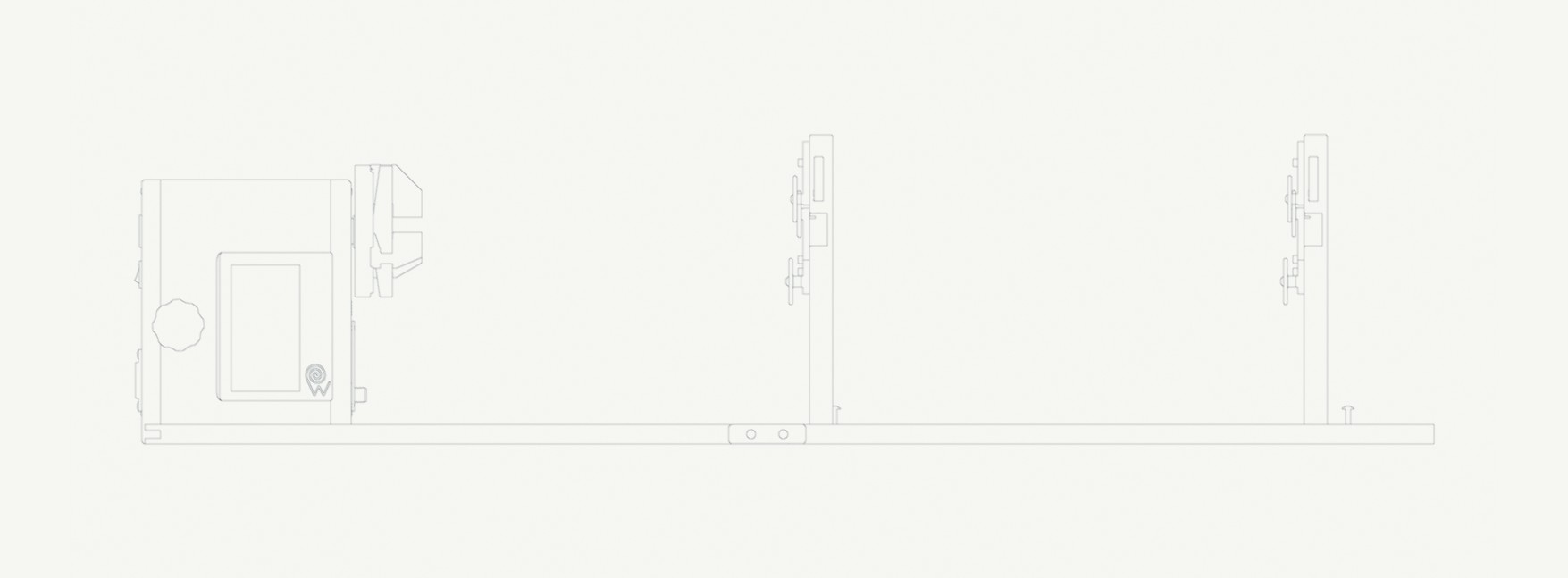
Dimensions are measured from the FRW CAD. Operating values come from the operator manual for firmware 4.0. Each row names its source.
| Overall length with the rail extension and rod supports | 1,008 mm | CAD |
|---|---|---|
| Overall width | 163 mm | CAD |
| Overall height above the bench | 240 mm | CAD |
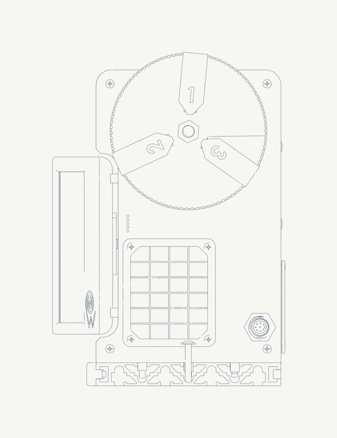
| Head unit, W × H × D | 151 × 216 × 223 mm | CAD |
| Spindle axis height above the bench | 165 mm (150 mm above the rail) | CAD |
| Rail | 500 mm aluminium base rail, 120 × 15 mm section; optional 500 mm extension joined with a connector | OWN |
| Rod supports | Optional, up to 2 with the extension; slide on the rail; 3 rollers Ø32 mm each, height 233 mm | CAD |
| Rod support mechanism | Iris type: the inner ring turns the three roller arms together; a spring closes them on the rod, a latch holds them open | OWN |
| Foot pedal, L × W × H | 178 × 136 × 219 mm | CAD |
| Chuck | Three-jaw, self-centring, Ø102 mm, clamped with the orange ring | CAD |
|---|---|---|
| Main shaft | Ø12.7 mm, length 188 mm, two ball bearings | CAD |
| Speed setpoint | 0 – 1000 rpm (limit adjustable 50 – 1000 rpm in 50 rpm steps) | MAN |
| Recommended wrapping speed | 60 – 150 rpm | MAN |
| Reverse | On the fly through zero; ramp 2 × the speed limit per second (300 → −300 rpm in about 0.3 s at 1000 rpm) | MAN |
| Turns counter | Signed, 0.1-turn resolution, counts manual rotation | MAN |
| Motor | Brushless outrunner, rotor Ø50 × 49 mm (5065 class) | CMP |
|---|---|---|
| Motor control | Field-oriented control with current limit in every mode | MAN |
| Transmission | Toothed belt, 2 motor turns per spindle turn; pulleys Ø30.7 mm and Ø15.0 mm outside | OWN |
| Current limit | 0.1 – 1.6 A in 0.05 A steps (default 1.00 A); a jammed spindle stalls at the limit | MAN |
| RPM | Pedal sets speed linearly up to the setpoint; 3 % dead zone; knob step 1 – 50 rpm | MAN |
|---|---|---|
| TORQUE | Pedal sets motor current, so torque and acceleration: 0 – 1.6 A at full pedal in 0.02 A steps; the spindle accelerates until the TORQUE speed limit, 10 – 1000 rpm (default 300), and is held there | OWN |
| INTERP | 0.1 – 2.0 turns per pedal stroke; detents off, 15°, 30°, 45°, 60°, 90°, 120°, 180°; holding current 0.05 – 1.6 A | MAN |
| DRY | 1 – 300 rpm for 1 – 240 min, three long beeps at the end | MAN |
| Drive | Stepper motor on a lead screw, lead 0.5 – 10 mm (default 2.0 mm) | MAN |
|---|---|---|
| Synchronisation | 0.05 – 20 spindle turns per mm in 0.05 steps; pitch = 1 / setting (2.50 → 0.400 mm per turn) | MAN |
| Travel | 5 – 300 mm limit (default 70 mm); disengages at the end, the spindle keeps running | MAN |
| Connection | M12 connector on the front panel; FRW and REV keys on the unit | MAN |
| Display | 4.3-inch class, 272 × 480 portrait, not a touchscreen | MAN |
|---|---|---|
| Knob | Rotary encoder with push button and vibration feedback | MAN |
| Foot pedal | Encoder input 0 – 100 %, 20 – 2000 counts full travel (default 200), home switch; SIDE and BACK buttons | MAN |
| Signals | Buzzer with seven distinct signals, status LEDs | MAN |
| Emergency stop | Hold BACK on the pedal for 2 s on any screen | MAN |
| Mains | IEC C14 inlet with power switch | MAN |
|---|---|---|
| Power supply | Internal open-frame unit, 300 W class | CMP |
| Cooling | 60 × 60 × 26 mm fan with fan-warning | CAD |
| Protection | Current and speed limits, driver and sensor monitoring, watchdog; a critical fault cuts both motors | MAN |
| Firmware | 4.0; settings return to defaults at power-up (non-volatile storage planned) | MAN |
Orthographic views generated from the FRW CAD, with the main dimensions in millimetres. CAD linework, not a manufacturing drawing; no tolerances are given.
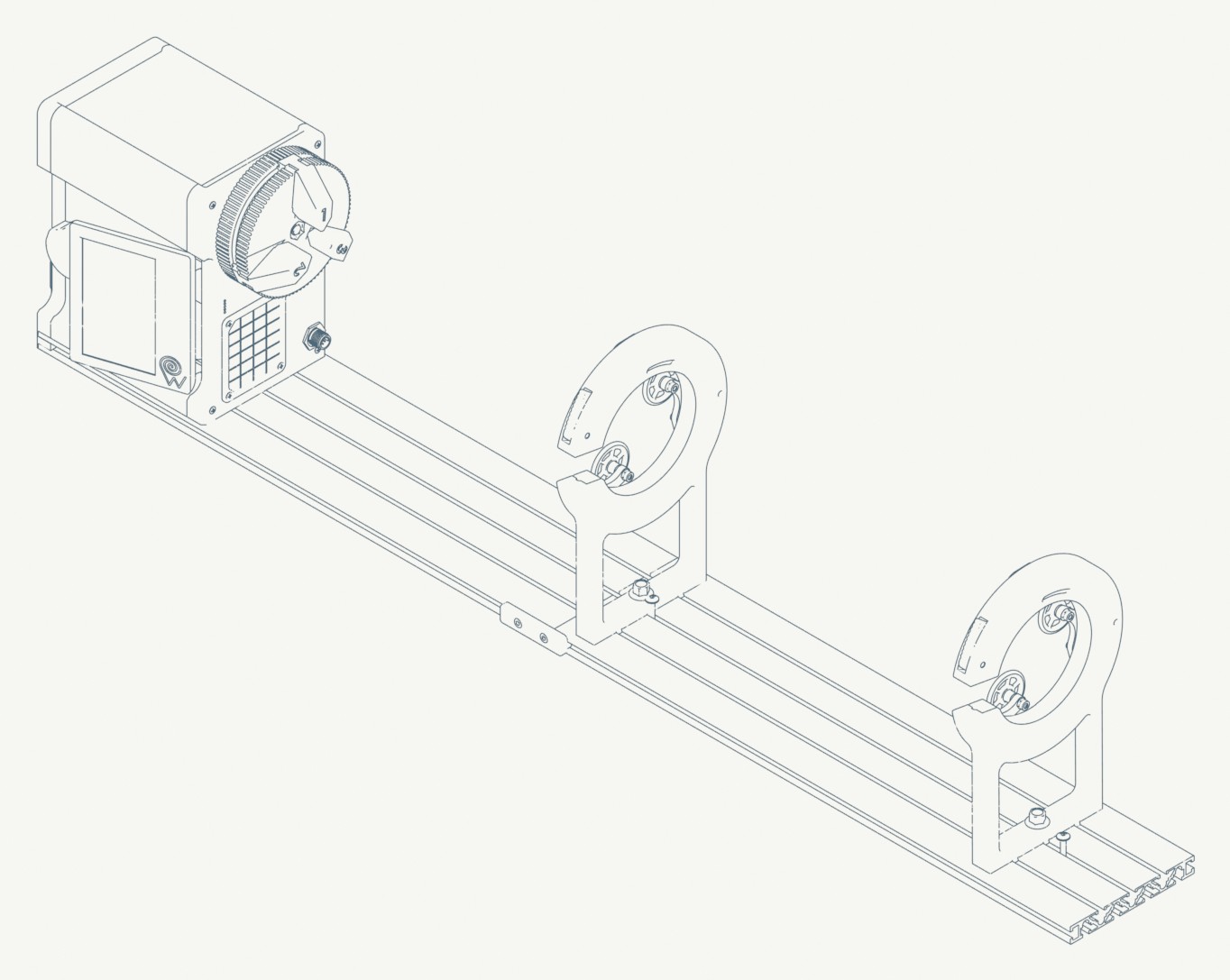
31 parts of the FRW4 design are printed parts: the housing, the chuck and its jaws, the rod supports and the pedal. They can be replaced or modified with a 3D printer.
Rod supports and accessories mount on the 120 × 15 mm aluminium rail. Add-ons: an extra thread-guide kit, a bench-mount kit and a printable spare-parts set.
Print files, materials and print settings come with the first production batch. See the parts catalogue →
The FRW4 Operator Manual, edition 1.3, 27 pages: modes, settings, signals, service and troubleshooting. The web version keeps every diagram and screenshot and adds search.
The tools around the machine and when they are available.
FRW4 is in its first production batch. Send an email-verified preorder request to reserve a machine. No payment is taken now; we confirm the price and the delivery date when we accept your request.
REQUEST A PREORDER ↗No registration or payment required to send a request. Email verification required.